products
HomeProducts508-1626mm Flying Welding Spiral Welded Pipe Unit Production Line

508-1626mm Flying Welding Spiral Welded Pipe Unit Production Line

Spiral welded pipe is an important type of steel pipe, which is widely used in the transportation of fluids such as water, oil, and natural gas, as well as engineering fields such as structure and piling. Since spiral steel pipes can be continuously produced from steel pipes of one width, production automation is easy to achieve. The spiral steel pipe machine is used to manufacture spiral seam welded pipes. It can produce steel pipes of different diameters from strip steel of the same width, and steel pipes of the same diameter can be produced from strip steel of different widths. 
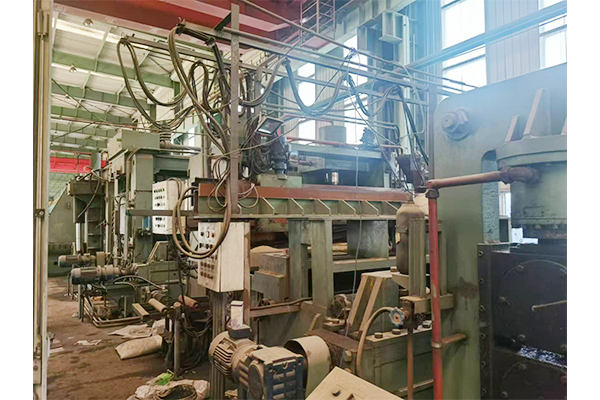
This set of spiral welding machine swings back. The adjustment of the forming angle of the back-swinging spiral welded pipe machine is through the adjustment of the rear axle that can rotate around the forming turning point. The equipment in the process preparation section is installed on the flying welding truck, which can achieve continuous and uninterrupted production. 
This machine is equipment from a Chinese state-owned enterprise. After producing 20,000 tons, it has been idle. The production time of this machine is: the downtime in 2011 is 2019.
I. Host technical parameters

Raw material parameters

Material

Strip thickness

Strip width

Inner diameter of tape roll

Outer diameter of tape roll

Coil width error

Roll weight

X42、X70、X80

6 ~25.4 mm 

800~1800 mm

Φ650~Φ760 mm

Φ1300~Φ2200 mm

≤±5 mm

≤45 t

Finished product parameters

Outer diameter

Steel tube wall thickness

Steel pipe pitch

Steel pipe weight

length

Product implementation standards

Φ508~Φ1626 mm

6 ~25.4 mm

Max 2350 mm

Max 16 T

8~15.5m

API5L

Unit parameters

Unit form

Molding direction

Molding mode


Forming angle

Down-pipe method

Delivery speed

Welding speed

Welding equipment

Butt welding method

Host installed capacity

Back-swinging, continuous production

Right-handed

Three-roll bending forming all-inclusive, externally controlled roll type sizing adjustable, auxiliary universal forming

40°08′~84°23′

Pipe pulling trolley unloading pipe

0.5-3.5 m /min

0.5-3.5 m /min

Double-sided submerged arc automatic welding

Submerged arc butt welding

850 KVA

Power source parameters

Voltage

Air compressor

220/380V   50HZ 

0.6Mpa,0.9m3/min

II.Φ508-Φ1626 process flow and production capacity
Host process flow chart:  
Coiling → uncoiling → uncoiling → straight head → three-roller pinch → neutral roller (1) → seven-roller leveling → neutral roller (2) → shear butt welding → neutral roller (3) → feeder → neutral roller (4) → fly welding car (The above process is carried out on the fly welding truck) → Steel strip storage transition section → alignment neutral roll (5) → rough milling machine → chip removal → alignment neutral roll (6) → precision milling machine → chip removal → panel cleaning → alignment neutral roll (7) → delivery machine → alignment neutral roll (8) → pre-bent guide plate → vertical roll before forming → inner welding → outer welding → centralizer guide → fly cutting → driving roller output → steel pipe pull-out
IV. Supply details and introduction of Φ508-Φ1626 fly welding equipment
1. Equipment supply details: 

No.

Name

QTY

 Remark

Host device

1

Coiling car

1


2

Uncoiler

1

Double cone head

3

Uncoiling straight head

1


4

Three-roll pinch

1


5

Electric vertical roller

8


6

Seven-roll leveler

1


7

Shear butt welding

1


8

The feeder

1


9

Flying welding vehicle

1


10

Storage transition roll

1


11

Edge milling machine

2


12

Panel cleaning

1


13

Delivery machine

1


14

Pre-bent guide plate

1


15

Pre-forming vertical roll

1


16

Molding machine

1


17

Internal welding device

1


18

External welding device

1


19

Rear axle

1


20

Flying cutter

1


21

Centralizer

1


22

Transportation and management trolley

1


23

Buried member

1


24

The base machine's hydraulic system

1


25

Main engine electrical system

1


Outsourced supporting equipment

1

DC-1500 welding machine

2

Made in US Lincoln

2

AC-1200 welding machine

2

Made in US Lincoln

3

Plasma cutting machine LGK-300

1

Made in China

4

Air compressor 0.9m³

1

Made in China

5

Butt welding trolley

1

Made in China

6

Flux processing device

1

Made in China

Explanation: 1) The power sources of electricity, water and gas in the workshop are provided by the user. 2) The hydraulic system does not contain hydraulic oil. 3) The lubricating oil used for the reducer is provided by the user.
2.Equipment introduction:
2.1 coiling car
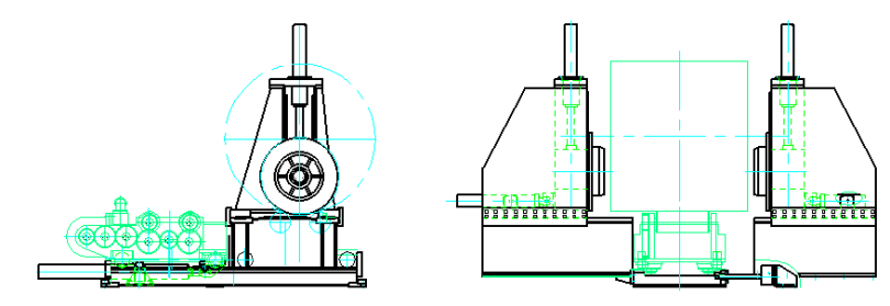
Function: Carry and slowly transport the steel coil to the uncoiler for timely and smooth unwinding Composition: walking mechanism, lifting oil cylinder, steel coil idler, driving motor
Motor: 15KW Roller diameter: 330mm Maximum load load: 45T

2.2 Function: Carry the steel coil, drive the steel coil to rotate, and use a straight-headed blade to uncoil it. Composition: Double cone head, driving device.

2.3 Unwinding straight head device:
Function: Use a blade to open the steel coil and bring the plate head into the straight head machine Composition: blade mechanism, three-roll straight-head machine Motor: 15KW Upper roll diameter: 320mm Lower roll diameter: 330mm

2.4 leveling machine
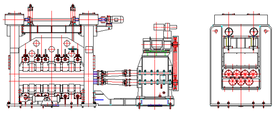
Function: Straighten and convey the steel strip sent by the unwinding and straightening machine forward. Structure: It mainly consists of four upper and three lower leveling rollers and transmission devices. Clamping, feeding and pressing method: motor-driven worm gear and worm pressing, electromechanical control pressing. Leveling roller diameter: 260mm Main motor: 110KW

2.5 Electric vertical roller:
Function: Electric centering, two-way adjustment, which plays a role in adjusting, centering and lateral guiding and guarding the strip. Structure: Consisting of transmission device, vertical roller device and base, adjusted by lead screw and nut.

2.5 Shear butt welding device:
Function: Cut the plate head and plate tail, butt and mill the plate head and plate tail to form grooves, and then weld them, and then mill off the elevated part of the weld seam. During butt welding, the head and tail of the steel plate are clamped by pressing down on the upper plate, and the head and tail are clamped by separate hydraulic clamping. The head and tail of the steel strip are pressed between the flux pad and the upper pressure plate; during welding, the flux pad can be lifted and pressed tightly against the lower surface of the steel strip;
Structure: It mainly consists of shearing device, groove milling device, weld milling device, butt welding table, front and rear pressing plates, etc. Milling method: mechanical Milling head feed: variable frequency speed regulation Cutting method: Hydraulic cylinder pressing Welding method: Semi-automatic submerged arc welding, welding speed: 0.5-3.5m/min Maximum shear force: 300T Main cylinder: 400mm×2
Welding machine: DC-1500 submerged arc welding machine AC-1200 submerged arc welding machine

2.6 the feeder
Function: Push the steel strip forward synchronously with the delivery machine to avoid heavy pulling force on the fly welding vehicle. Driving method: DC motor 37KW, with planetary reducer to drive pinch rollers Diameter: 400mm Speed regulation method: DC speed regulation, with brake

2.7 Flying welding vehicle 
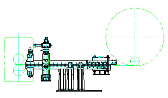
Function: Carrying equipment such as uncoilers, pinch leveler, vertical rollers, cutting and butt welding, feeding rollers, etc., and advancing with the steel strip during coil change and butt welding, achieving continuous production by keeping pace with the delivery speed. 
Flying welding vehicle travel: 47 meters 
Flying welding vehicle drive motor: AC motor Speed regulation 
method: AC frequency conversion Walking speed: 0.5~10m/min

2.8 Milling machine:
Function: Mill welding grooves on both sides of strip steel. 
Structure: It consists of milling head device, machine bed device, pressing roller device and other parts. Milling cutter driving method: AC frequency conversion Milling depth: maximum 15mm Milling speed: 135-180m/min. 
Milling accuracy: plate width error: ±0.5 mm; straight edge width error: ±0.3 mm; Groove angle error: ±2.5°; 
Groove shape: 30° in X direction, 30° in I direction Steel strip speed: 0.5-3.5m/min; 
Cutter head transmission: gear transmission; 
Milling cutter driving method: AC frequency conversion speed regulation Surface roughness after milling: 6.3 Motor: 55KW Cutter head: 720mm

2.9 Panel cleaning device
Remove iron filings and debris left on the surface of the strip after edge milling Cleaning is equipped with a limit device to prevent the cleaning belt from falling off during work; 
The cleaning device has a cleaning belt tension adjusting device

2.10 Delivery machine:
Function: Generating power for strip steel to move forward and control forming speed. 
Structure: It consists of frequency conversion speed regulating transmission, delivery roller assembly, frame, plunger pump and other parts. 
Delivery speed: 0.5~3.5/min Transmission method: Double reducer Speed regulation 
method: DC speed regulation motor 55KW 
Delivery roller diameter: 620mm

2.11 Guide plate:
Function: Bend the strip edge unilaterally before entering the forming machine, and prevent the strip from bending and bowing before entering the forming machine. It is required to have the roller's own protection function, which can achieve normal operation when the plate thickness changes and ensure normal strip steel delivery. 
Structure: It mainly consists of pre-bending device, guide plate device and base.

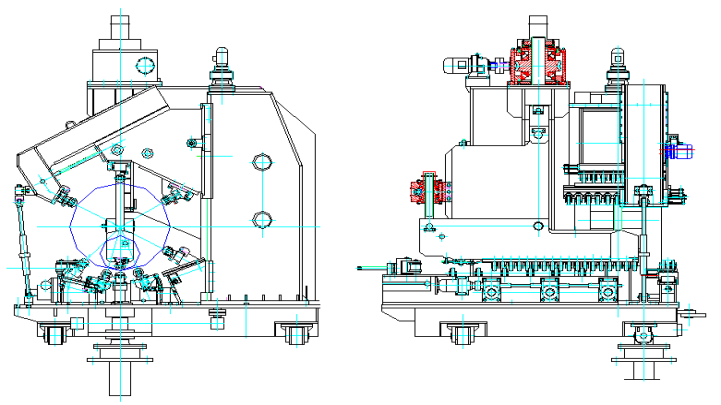
2.12 Forming machine:
Function: This machine is a unit forming equipment, which is used to force the steel strip to bend and deform to generate steel pipes for welding. 
Model: The height of 1#and 3#rollers is electrically adjusted, and the distance between 1#and 3#rollers is electrically adjusted. 
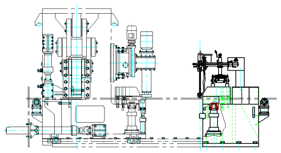
Structure: It consists of base, rotary shaft, vertical roller, tensioning device, 1#, 2#and 3#forming rollers and 4#, 5#, 6#, 7#, 8#external control rollers. Unit type: rear swing rollup right screw. 
Adjustment method: Three-roller bending external control roller and full-roller adjustable. Strip positioning method: edge positioning. Forming range: Φ508~1626mm Forming machine rotation mode: Then the bridge swings together

2.13 Internal welding device:
It is used to fix and adjust the inner welding head to ensure that the welding head centers on the weld seam and welds well, meeting the adjustment of the front, back, up and down, left and right of the twin-wire welding head, making it more convenient and flexible.

2.14 Rear Bridge:
Function: The carrier of hosting equipment, pipe outlet equipment, fly cutting trolley and other equipment behind the forming machine swings at an angle to form a forming angle, ensuring that the unit uses steel plates of different widths to produce products of various diameters.

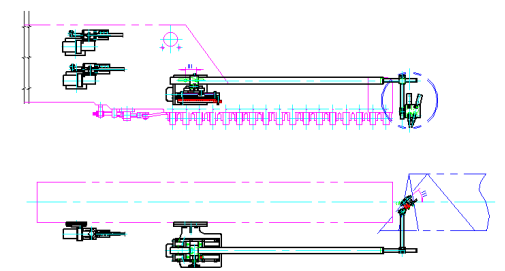
2.15 Flying cutting trolley:
Function: Used to cut formed and welded steel pipes into finished pipes of fixed length according to fixed length. 
Structure: It mainly consists of base, pneumatic system, car body, jacking wheel device and walking mechanism. 
Cutting method: plasma cutting

2.16 transportation and management trolley
Function: Catch the steel pipe cut from the rear axle and send it to the conveyor roller table. Two motors drive the trolley to walk to ensure that the trolley will not roll when dropping the pipe.
Speed regulation method: AC frequency conversion

2.17 Main engine embedded parts:
Load-bearing guide rails for fly cutter and rear axle, including guide rails, anchor screws, etc.
2.18 Main engine hydraulic system:
(1) The main engine hydraulic system consists of two parts: the front axle and the rear axle hydraulic system.
(2) Working medium: Anti-wear hydraulic oil, YB-N46, is recommended. 
(3) The coil control voltage of the solenoid valve is DC24V.
(4) Hydraulic instructions: Hydraulic station: composed of oil tank device, main pump device, etc., with a high working pressure of 16mpa and a low pressure of 8mpa. Forced cooling: Use a water cooler for forced cooling.
2.20 Main engine electronic control system:
(1) The main engine electrical system is used to operate and control each single equipment of the entire large-diameter spiral welded pipe production unit. It is a non-standard design electrical control system. Control range: uncoiler ~ rear axle 
(2) The electronic control system consists of a PLC automatic control system, an AC speed control system, and a digital display system. The system design and component selection comply with IS9001 and CCC standards. 
(3) The system design of machinery requiring speed regulation is equipped with automatic balanced adjustment of speed parameters and manual continuous adjustment functions. 
(4) The electrical system is equipped with an automatic board speed display system. 
(5) Motors above 22KW (without speed regulation system) are equipped with step-down start.
(6) The AC frequency conversion device equipped with the system is equipped with input reactors to reduce pollution to the power network side.
(7) The control function of the electrical system is designed to be closely integrated with the unit process, stand-alone equipment, and hydraulic system, and can be controlled accordingly.
Party B provides technical data: 
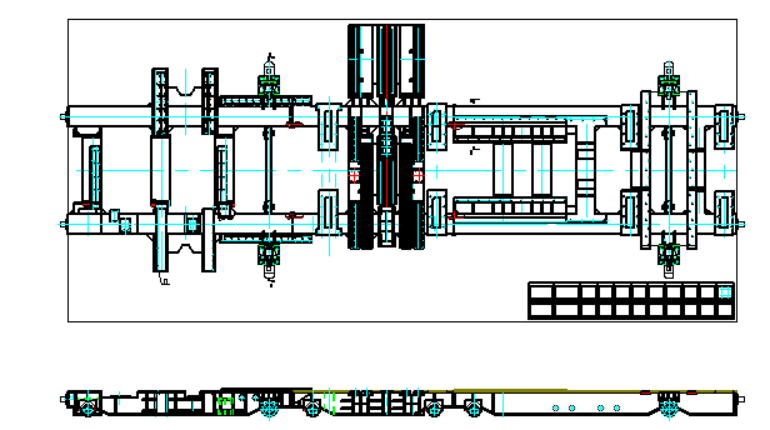
General layout plan of unit equipment 
Hydraulic schematic diagram and piping diagram of unit equipment 
Electrical schematic diagram and wiring diagram of unit equipment 
Drawings for unit equipment installation 
Unit operation and maintenance instructions 
Basic drawings of unit equipment
×

Contact Us

captcha